This document describes how to replace the electronic circuit board found in a 1969, 1970, and 1971 Ford electronic engine governor (also called a rev limiter) with a modern circuit board manufactured by Pertronix and installed in their digital rev limiter product. The project requires disassembly of both limiters and modification of the Pertronix circuit board to work inside the Ford case. Basic soldering skills are required.
You can also use this procedure to make a working rev limiter from an empty Ford case and reproduction wiring harness. Ford used the same case to house an electronic voltage regulator that was used on Ford cars and trucks. Reproduction cases can also be used, but do not use a plastic case! A metal case is needed for reasons that are described below.
WARNING: This procedure will undoubtedly void the manufacturer's warranty provided with the digital rev limiter by Pertronix. Pertronix and Muscle Car Research LLC are not responsible for any damage to your vehicle or to the limiters that you modify by following the procedure described here. Continue at your own risk.
Note: I strongly recommend that you first test your Pertronix limiter by temporarily installing it using the provided wiring. You want to be sure that your limiter is working properly before you modify it in any way.
Tools needed:
|
|
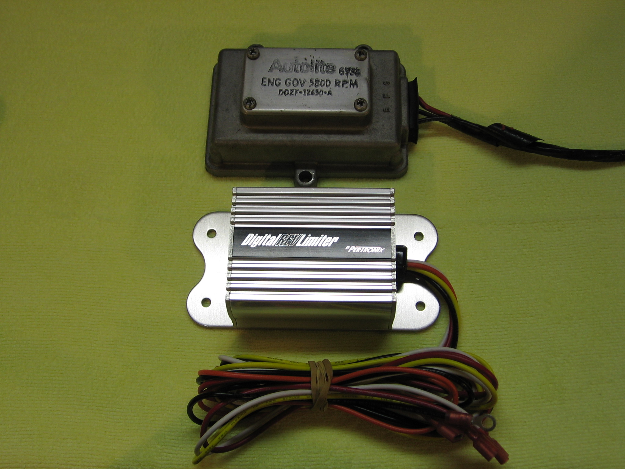
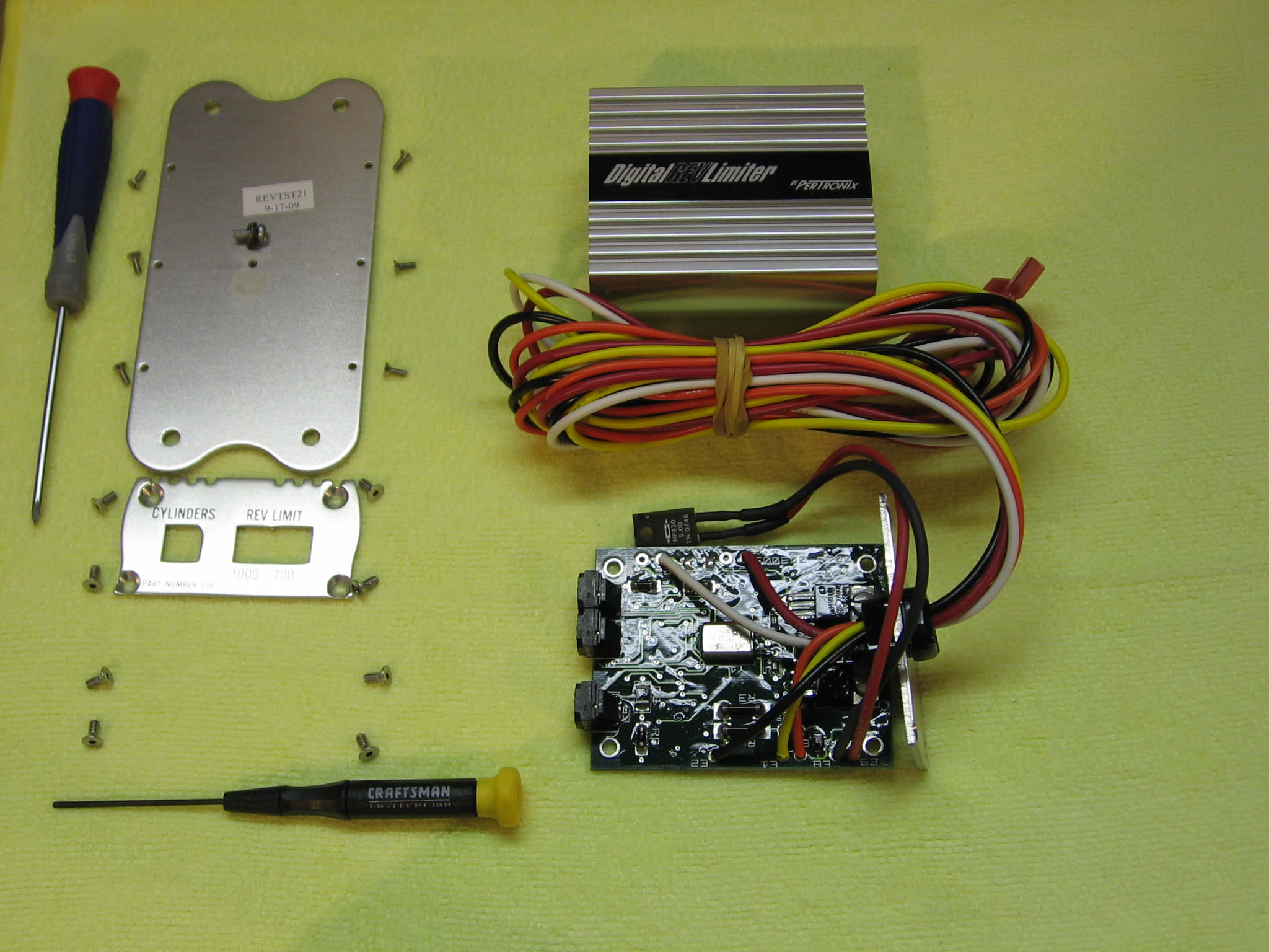
Larger, more detailed images can be viewed by clicking on the images below. Start by collecting the limiters and the tools described above. The Ford limiters are identified with an engineering number that's stamped on the cover. The 5,800 RPM limiter is stamped D0ZF-12450-A. The 6,150 RPM limiter is stamped D0ZF-12450-B. Note that the Pertronix limiter can only be adjusted in increments of 100 RPM. It can thus be adjusted to match the 5,800 RPM limit of the -A limiter, but the 6,150 RPM limit of the -B limiter will need to be approximated at either 6,100 or 6,200 RPM. The choice is yours depending on your comfort level.
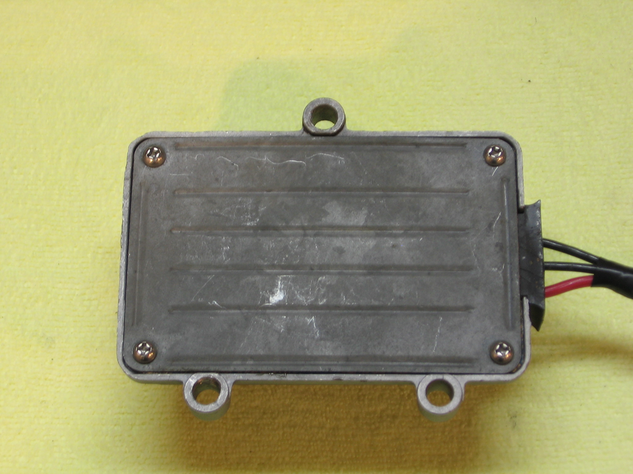
Let's get started! Here are the two limiters:
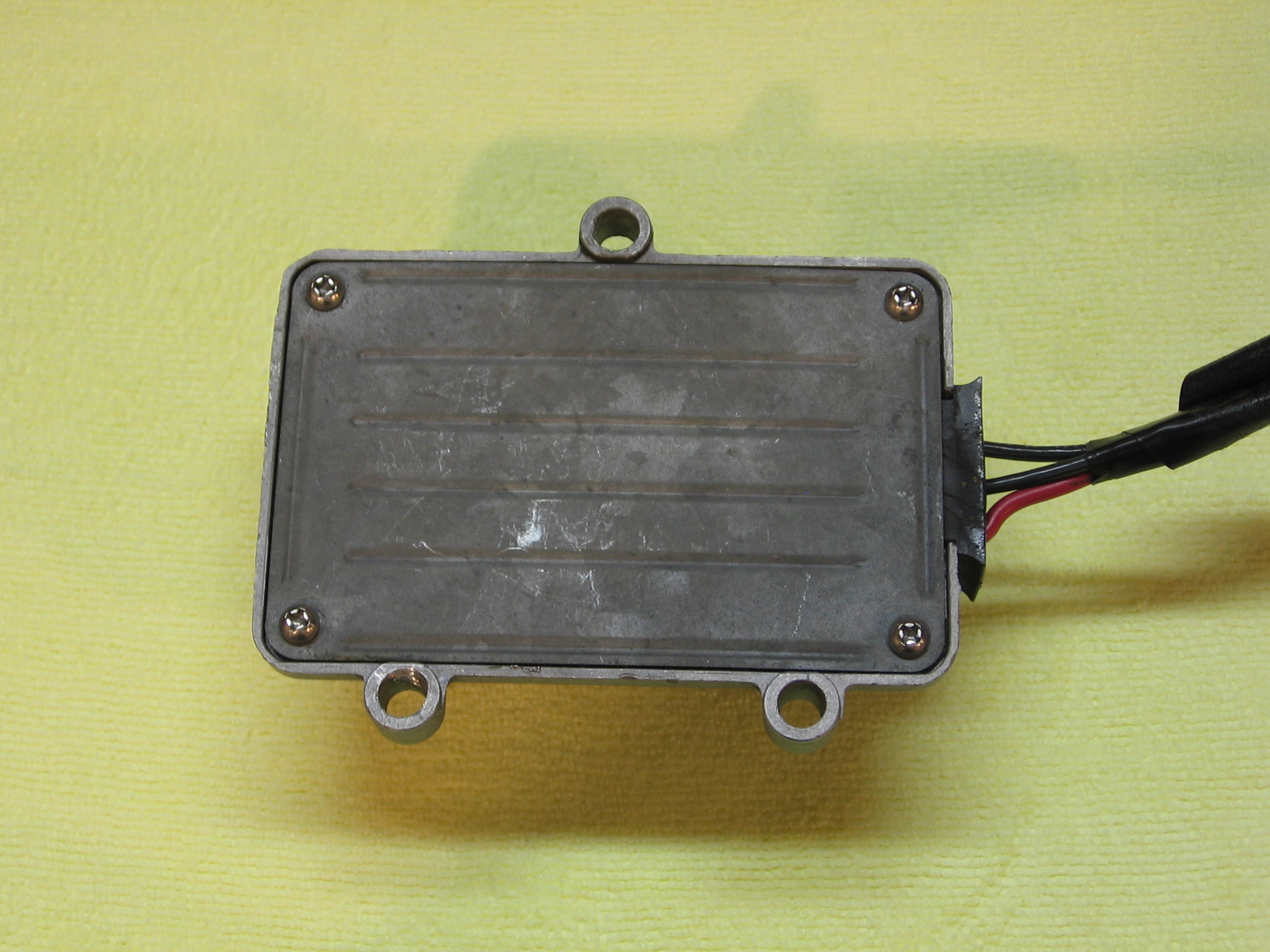
Start by removing the rear cover from the Ford limiter. Flip it over and you'll see four phillips head screws. Remove them using the phillips screwdriver.
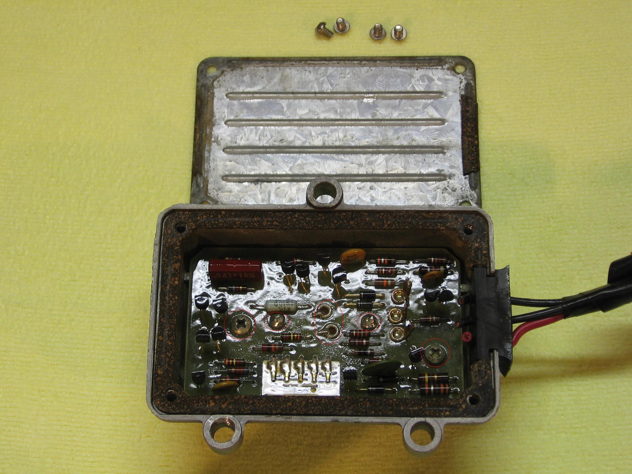
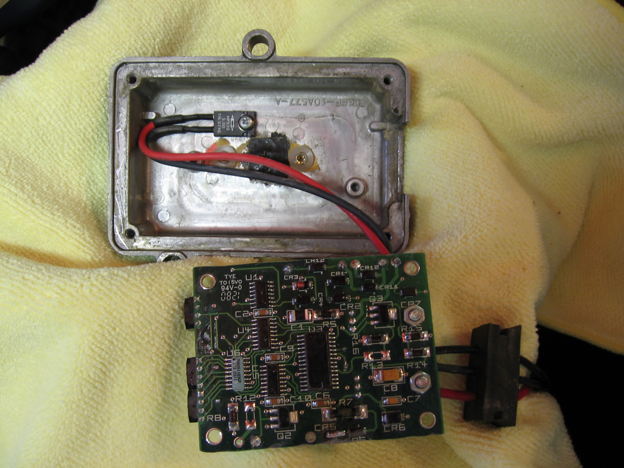
Lift off the cover to expose the circuit board. To remove the board you'll need a phillips screw driver, a soldering iron, wire cutters, and possibly the drill. The areas to be addressed are circled in red below. Remove the screws using the screwdriver. Use the soldering iron to remove the solder holding the board at the other four points. You may need to drill out the two outermost soldered points. Clip the wires holding down the board at the two inner points and lift out the board when all six points have been addressed. A dental pick can be used to help lift the board while you're working on the soldered points.
If your circuit board has never been modified you'll also need to remove the three wires from your Ford wiring harness. Use your soldering iron to separate the soldered joints and remove each wire from the board. The wires shown in the picture below were previously detached and trimmed.
Remove the board from the case and lay it aside.

Now turn your attention to the Pertronix limiter. The circuit board is inside an aluminum case. You need to remove the bottom and both sides of the case to extract the circuit board. Let's start with the bottom. Remove the six hex screws with the 0.05" hex screwdriver.

Here's the Pertronix limiter with the bottom plate unscrewed. The component screwed to the bottom plate is a power resistor. Remove the screw that holds it to the bottom plate. Now move to the sides.

The plate on each side of the Pertronix limiter is held in place with four hex screws. Remove them with the 1/16" hex screwdriver.
The circuit board can be pulled from the case after the screws are removed from both sides. Here's how it looks after it's been disassembled.
Now comes the tricky part: modifying the board to use the Ford wiring harness and to fit in the Ford case. Let's start with the wiring harness.
The Ford wiring harness contains a red wire for power, a black wire for the distributor lead, and a black wire for ground. Identify the ground wire using the continuity tester and mark it clearly so that you don't confuse it with the black distributor lead wire. Be very sure that you have it right - if you cross these wires you will probably fry the Pertronix limiter when you install it! On my Ford harness the ground wire was the middle wire.
Be very careful with these next steps. If you damage the Pertronix wiring or circuit board your only recourse is to buy another limiter and start over.
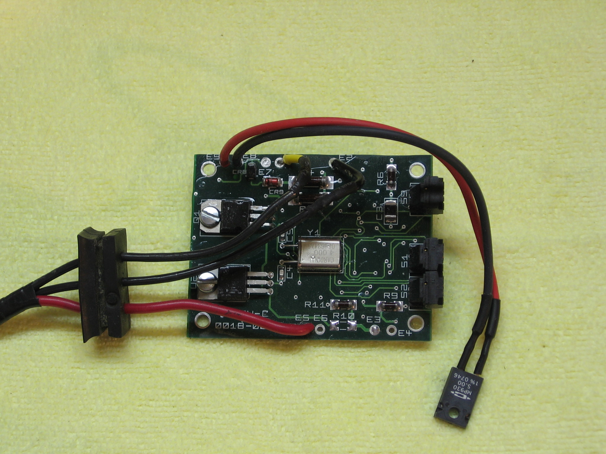
Turn your attention to the wires on the Pertronix circuit board. You're going to use the red wire for the red Ford power wire, the black wire for the black Ford ground wire, and the yellow wire for the black Ford distributor lead wire. The orange and white wires aren't used. They can either be removed with your soldering iron or cut and sealed. I removed them with a soldering iron.

Once you've addressed the white and orange wires you can focus on the red, black, and yellow wires. You can remove them and re-solder the Ford wires in their place, but I don't recommend this approach unless you have good soldering skills. As an alternative, you can cut the wires (leave 3-4" or so), strip the ends, and solder them to the corresponding Ford wires using rosin core solder. Seal the soldered joint with heat shrink tubing when done. Both rewiring options can be seen in the picture below (the red Ford wire is soldered to the board and the two black Ford wires are joined to their Pertronix counterparts with soldered splices). Test each wire from end-to-end with your continuity tester after you've finished soldering.
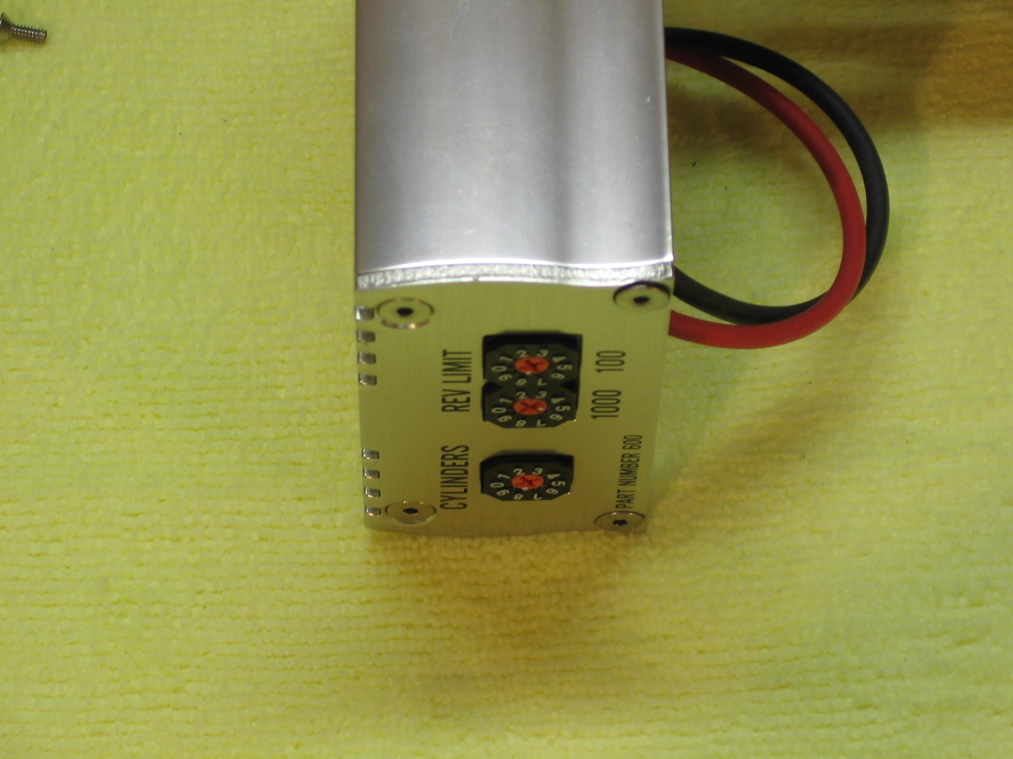
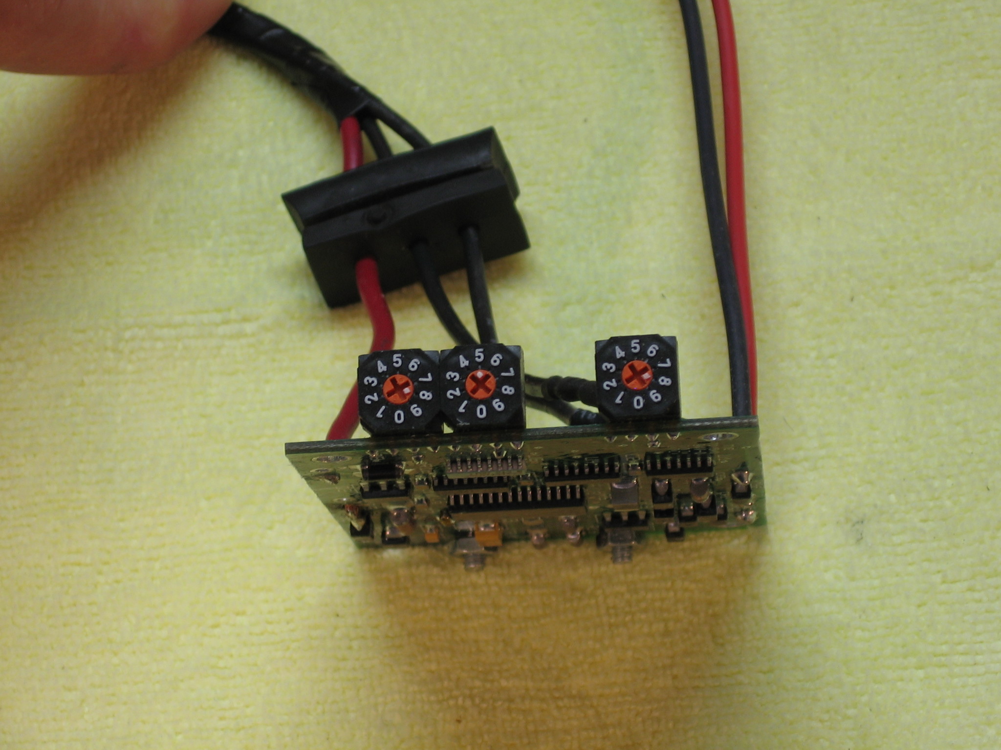
With the wiring work finished you can set the rev limit using the switches on the end of the circuit board. Set the isolated switch (the one on the right in the picture below) to "8" for eight-cylinder operation. The middle switch marks thousands of RPMs and the outer switch right next to the middle switch (the one on the left) marks hundreds of RPMs. I've set the switches for 5,800 RPM on an eight cylinder engine.
NOTE: At this point I recommend setting the switches to 2,000 RPM to make installation testing easier - you don't want to try testing it at 6,000 RPM, do you? You can adjust the switches to their final position after you're sure that the limiter is working properly.
Now back to the Ford case. Use the rear cover as a template to form two gaskets: one for the inside top of the case, and one for the rear cover. Trim with a utility knife as needed. Mark holes for the rear cover and punch them through using one of the pointy tools you have on-hand.

If you try to fit the Pertronix circuit board into the case you'll notice that it's a bit (about 0.1") too wide. Use the rotary tool and grinder to remove about 0.05" of material from each side of the board. Again, be careful with this step! You do not want to grind into the printed circuit!
Continue to grind and test fit the board until you can lay it inside with no interference. Place a single drop of thermal paste (available from computer and electronics suppliers - search for "Arctic Silver" if you need sources) on the bottom of the power resistor.
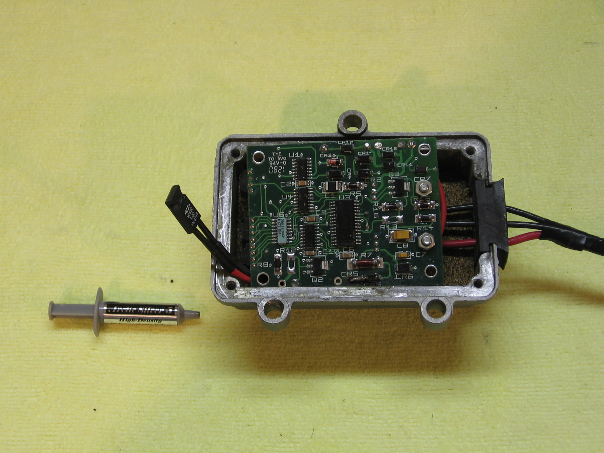
Now remove the board and drill a 5/64" hole in the location shown below. Thread the hole using the 7/64" tap. Attach the power resistor using the same screw that was used to mount the resistor in the Pertronix limiter. The resistor needs to be firmly mounted to a metal surface that serves as a heat sink - this is why a metal case is needed!
 |
 |
Reinstall the inner cork gasket and place the circuit board inside the case. Install the outer cork gasket and reinstall the rear cover using the four phillips screws.
That's it for the modification! Your limiter is now ready for installation and testing.

Test the limiter by wiring it into your ignition circuit and installing the limiter on your fender apron. If you set the switches to 2,000 RPM you should be able to test the limiter by trying to run the engine beyond 2,000 RPM. If the limiter is working properly you won't be able to. If the limiter isn't working properly you either messed something up or you have a defective limiter. Consult the installation instructions provided with the Pertronix limiter for diagnostic procedures. One easy test with a multimeter is to check the voltage at the white wire while the car is running - it should measure approximately 2.5V DC.
One other note: I ran into an interesting issue when testing my prototype. I originally installed the board with a fairly tight fit. While doing run time testing I found that my car would run fine at first, but the engine would eventually run rough and shut down at idle speed. While troubleshooting I found that everything worked fine as long as the limiter wasn't mounted to the fender apron. With some experimentation I discovered that loosening one screw on the apron would eliminate the problem. I can only speculate that tightening the screw was somehow altering the case enough to squeeze something on the board that had an affect on the limiter. I was able to eliminate the problem with a little more grinding to make the board fit inside the case a little less tightly. I had the power resistor touching the case lightly without being screwed down at the time; perhaps it was overheating?
- Log in to post comments