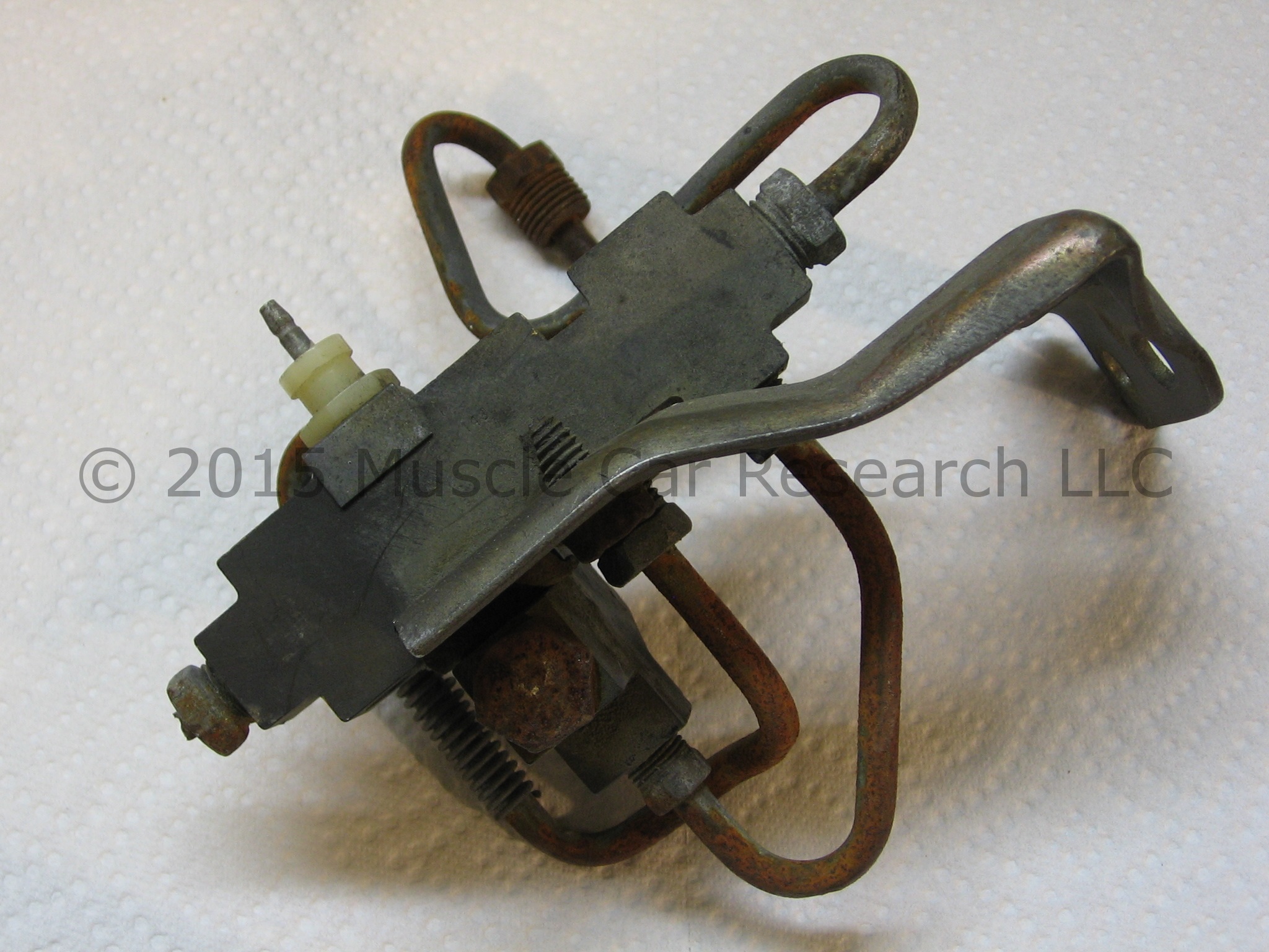
This Weatherhead brake pressure distribution switch was removed from a 1970 Chevrolet Camaro. The original GM part number for this part is 3983040. I have not found any references to this part being used on other GM vehicles; please contact us if you know otherwise. You can click on the pictures below to see larger versions of the images.
I've seen another switch that looks very similar to this one with the exception of a threaded port and plug on the boss next to the switch terminal. Please contact us if you know of other applications for these switches or if you can help explain the difference in these two switches.
I'm going to disassemble this valve to see if it's rebuildable. Follow along as I tear it down! Tools needed:
|
|
Start by removing the brake lines. Use flare nut wrenches if you intend to re-use the lines. It's easier to cut the lines and use sockets or box wrenches if you intend to replace the lines.

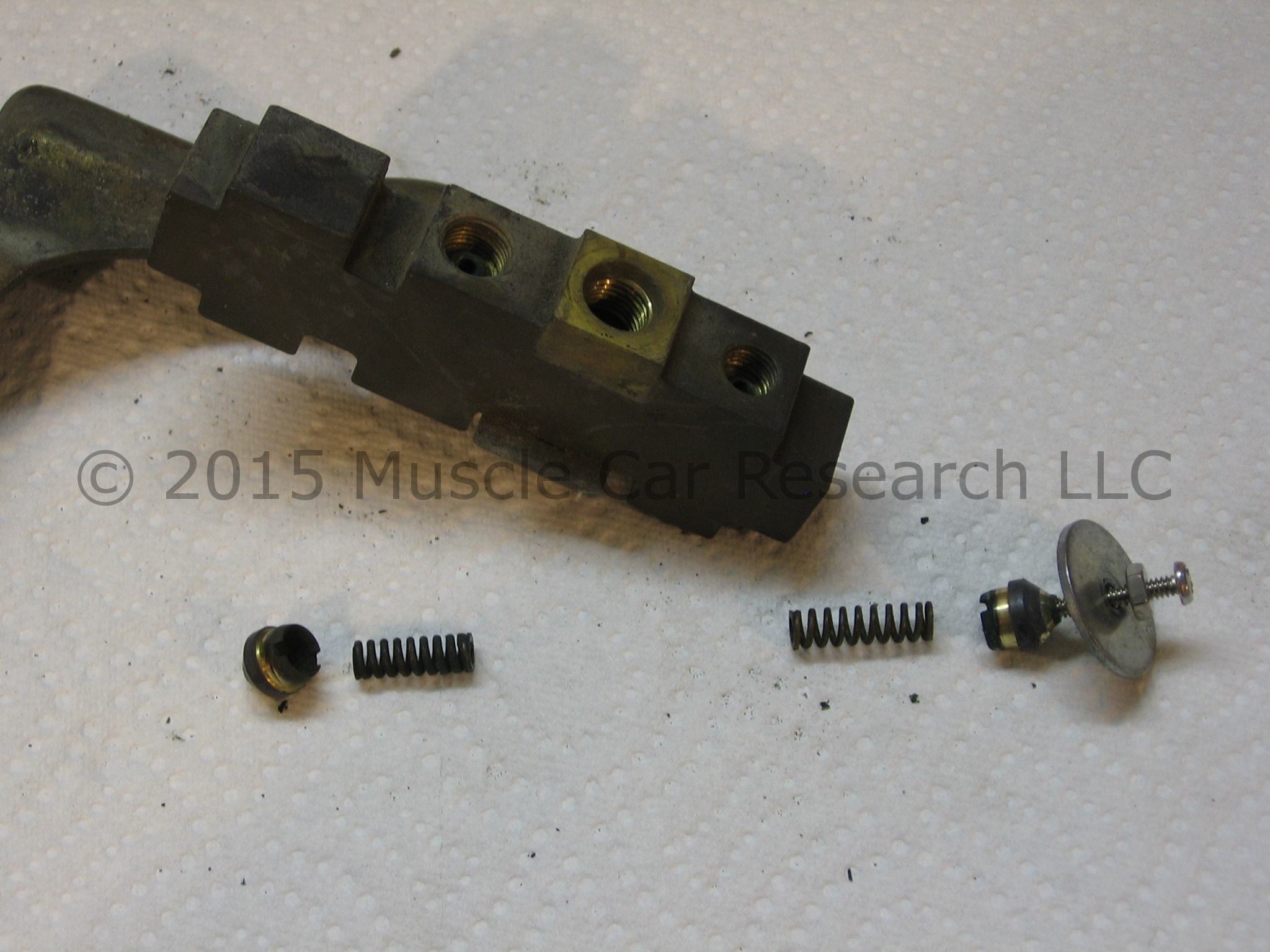
Now remove the switch terminal using the 5/8" wrench.

Note the o-ring used to seal the base of the switch. It might not come out when you remove the switch. Remove it with a dental pick if it stays behind as this one did.

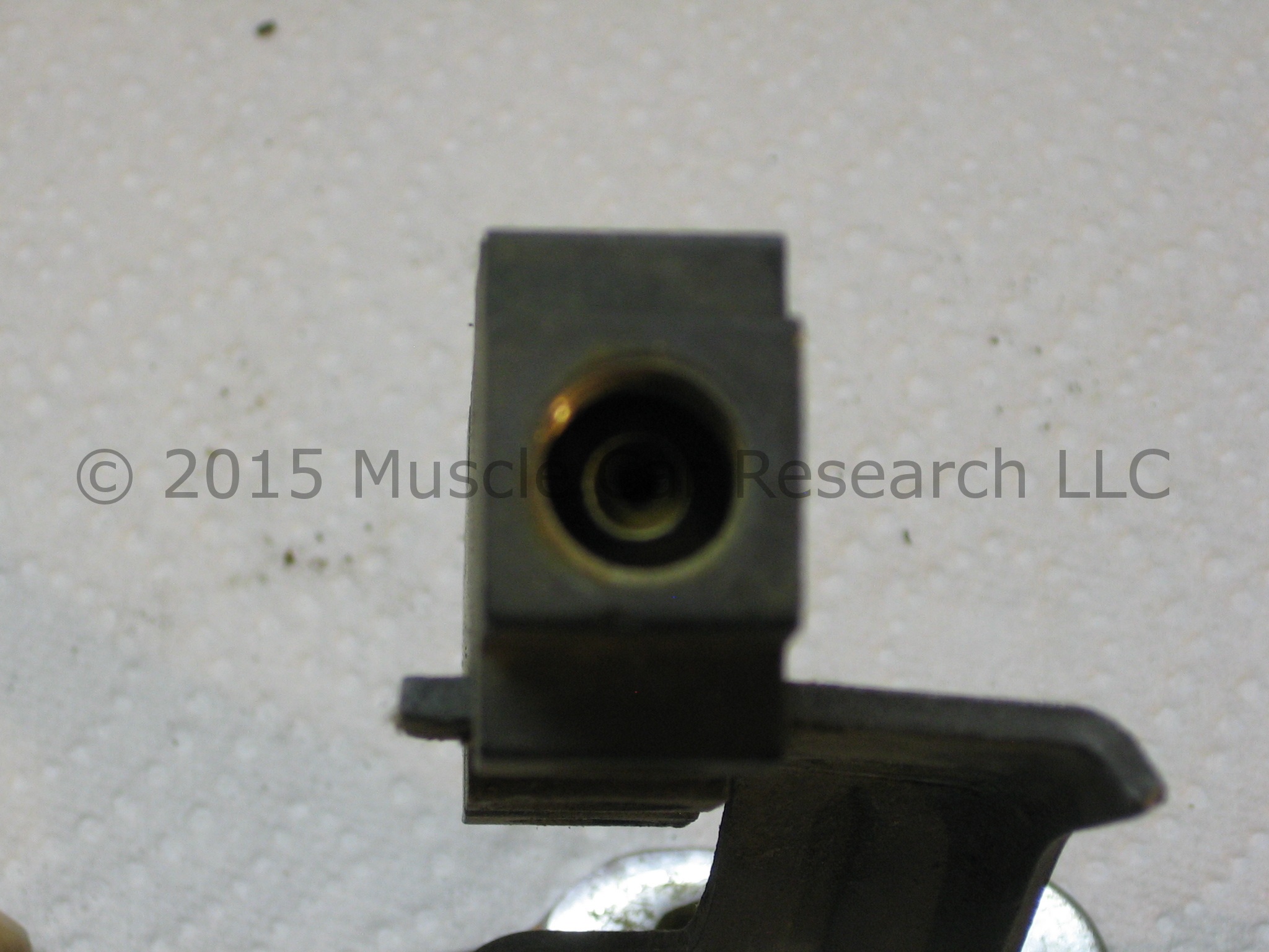
This part has no plugs or bolts that can be removed to gain access to the internal parts - you need to remove the brass tube seats from the ends of the body. They're pressed in and can be removed with a simple tool.
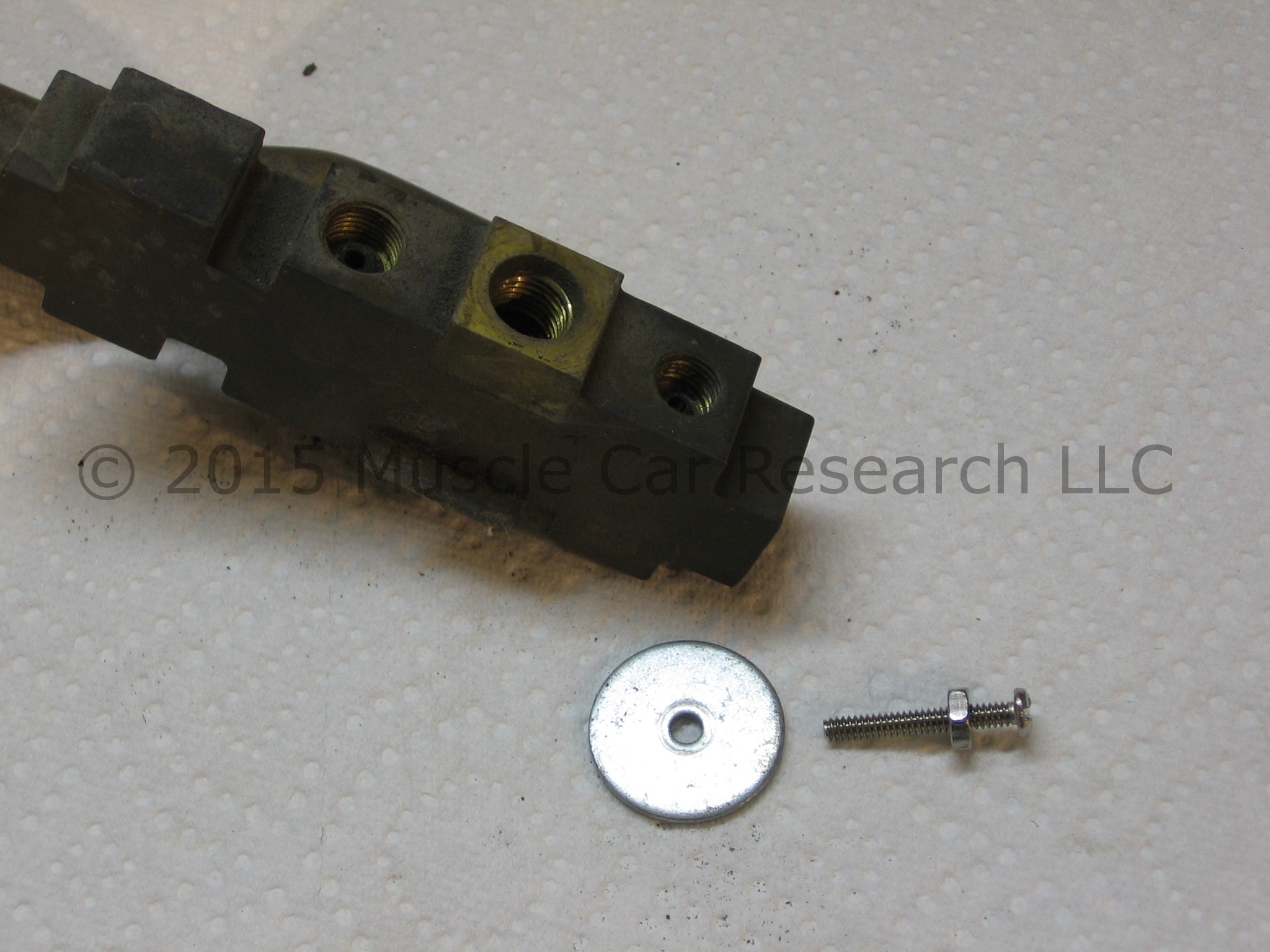
You can make your own puller tool using a 6-32 machine screw, a 6-32 nut, and a flat washer. You can also buy the complete puller tool from Muscle Car Research if you'd rather save some time.
Use the 6-32 tap to thread the hole in the tube seat. You might be able to thread the hole using the machine screw because steel is harder than brass. Thread the nut onto the screw, add the washer, and screw the tool into the tube seat.
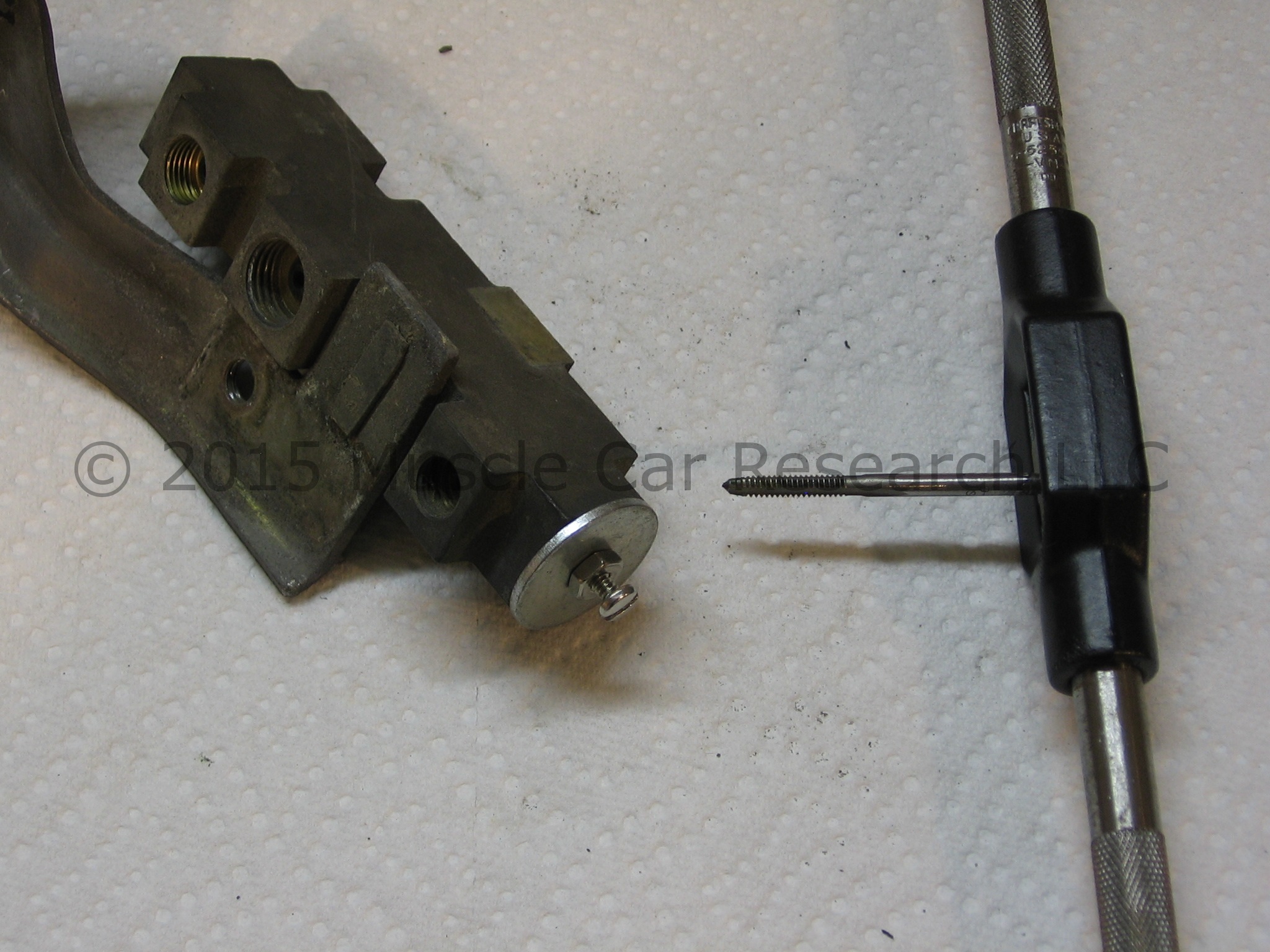
Remove the tube seats by turning the nut towards the washer. This will easily pull out the seats without the risk of damage to any other parts. You should find a spring under each tube seat - note that the one on the end away from the mounting bracket is slightly longer than the other.
With the tube seats out of the way you can remove the internal parts. Insert your punch into the bracket end of the body and push the parts out onto a shop cloth. You may need a few taps from a small ball peen hammer.
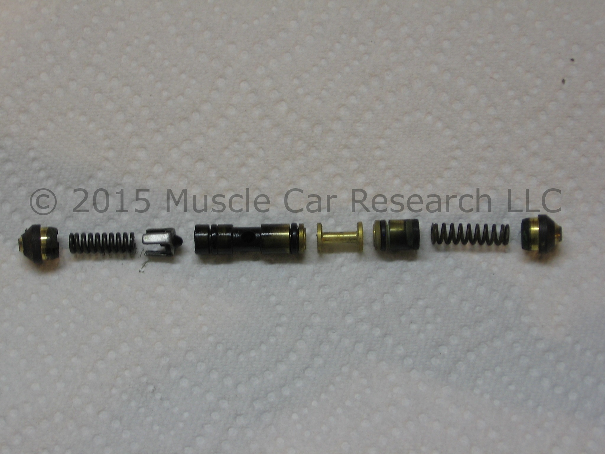
Note the arrangement of the internal parts! The assembly includes a series of pistons and spacers with three o-ring seals. Proper orientation is critical for the switch to work properly! A fluid leak from the terminal area means that one or more of your o-ring seals has failed.
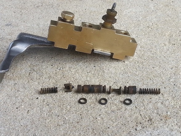
I've seen another valve that looks very similar to this one. Note the brass plug in the image below; the port this plug fills is missing in the valve pictured above. The large brass piston pictured below also appears to be slightly different. I'm still trying to figure out the original applications for these two valves. Please contact me if you can help identify them.
Muscle Car Research offers a rebuild kit for this switch with seals, springs, and tube seats. Complete rebuild instructions are available.
- Log in to post comments